
Why Can a Correct Machine Still Trip, Lose Pressure, or Miss Its Rated Speed?
Factories often plan utilities from one catalog number. They treat total power as breaker size, assume local voltage is compatible, and connect pneumatic modules to the nearest airline. The line may then suffer voltage drop, phase imbalance, nuisance trips, ultrasonic alarms, unstable air pressure, wet air, slow cylinders, and incomplete handle transfer. These faults appear to be machine problems but originate at the plant interface. Adding a printer, slitter, compressor, dryer, or extraction unit after the electrical design is finished makes the risk larger. A usable plan must separate connected load from operating demand, document starting and peak events, verify short-circuit and protective requirements, and measure compressed-air flow at the required point-of-use pressure. The Manufacturer and local engineer must agree on boundaries before a Customizable OEM or ODM line is shipped.
Size plant utilities from a complete load list, operating sequence, local electrical rules, measured pneumatic demand, pressure-drop calculation, and required air quality. Zhengxin supplies model-specific interface data so the buyer’s qualified engineers can design stable power and compressed-air systems.
The following application method helps importers, investors, and production engineers translate machine specifications into a coordinated plant topology. It covers load states, protection interfaces, power quality, pneumatic peaks, treatment and storage, then identifies the measurements needed during FAT, installation, and commissioning before commercial output is accepted.
Build a Complete Utility Load List for the Entire Line
List every machine and auxiliary device, not only the bag maker. Record rated voltage, phase, frequency, connected power, full-load current, starting method, duty cycle, control voltage, pneumatic pressure, average flow, peak flow, and air-quality requirement. Include printing dryers, chillers, corona treatment, exhaust, compressors, air dryers, lighting, lifting equipment, and future modules.
| Zhengxin reference model | Published voltage options | Published total power | Planning note |
|---|---|---|---|
| ZXL-B700 | 380 V / 220 V | 12 kW | Confirm phase, frequency, configuration, and auxiliaries |
| ZXL-A700 Ultra | 380 V / 220 V | 15 kW | Include punching and all contracted online modules |
| ZXL-E700 Ultra | 380 V / 220 V | 18 kW | Verify handle-attaching and pneumatic interface data |
Published values are selection references, not a final electrical design. The Supplier should issue the approved nameplate, electrical drawing, load schedule, and interface list for the delivered serial number.
Separate Connected Load, Demand, Starting Current, and Capacity Margin
Connected load is the sum of rated loads. Maximum demand depends on which loads operate together. Motors, heaters, ultrasonic generators, servo drives, and air compressors have different starting and cycling behavior. Size distribution using the approved load profile and local code, not by multiplying catalog kilowatts by an arbitrary factor.
- Create operating states for setup, warm-up, normal production, maximum production, cleaning, and shutdown.
- Identify the largest starting event and whether loads can be sequenced.
- Include voltage drop from transformer to machine during peak operation.
- Reserve documented capacity for contracted and realistic future modules.
- Verify protective-device coordination and fault level through a qualified electrical engineer.
A large breaker does not cure a weak feeder and can reduce protection. Cable size, installation method, ambient temperature, grouping, conductor material, harmonics, and national requirements must be evaluated locally.
Confirm Voltage, Frequency, Earthing, Power Quality, and Machine Safety
IEC 60204-1 applies to electrical, electronic, and programmable equipment of machines and addresses areas including overcurrent protection, protective bonding, EMC, power-drive systems, and technical documentation. The machine supply begins at the connection point defined in the design, while the building installation remains a site responsibility.
- Confirm nominal voltage, tolerance, phase sequence, frequency, and earthing system.
- Measure phase-to-phase and phase-to-earth values under load.
- Check voltage unbalance, harmonics, transients, and sensitive-control compatibility.
- Provide a lockable supply disconnect and protective devices as designed.
- Verify protective bonding and machine documentation after installation.
If a transformer, voltage stabilizer, reactor, filter, or uninterruptible control supply is proposed, define its purpose and rating. The Manufacturer should review any change that can affect drives, ultrasonic equipment, or safety circuits.
Calculate Compressed-Air Demand from Pneumatic Events
Do not size the compressor from pipe diameter or one pressure gauge. Create a device list for cylinders, valves, blow-off nozzles, grippers, punches, and actuators. For each event, record bore, stroke, cycles, operating pressure, simultaneous use, leakage allowance, and duration. Convert these events into average flow and peak flow at standard reference conditions.
| Pneumatic value | Why it matters | How to verify |
|---|---|---|
| Point-of-use pressure | Determines actuator force and timing | Measure at the machine during peak event |
| Average flow | Supports compressor energy and capacity | Flow measurement across a full cycle |
| Peak flow | Drives local pressure drop | High-resolution pressure and flow trend |
| Leakage | Raises energy cost and reduces reserve | Off-production leak test |
| Air quality | Protects valves, products, and print area | Defined sampling point and test method |
Ask the Supplier for consumption data by operating mode. If unavailable for a Customizable module, measure it during FAT rather than estimating after installation.
Design Distribution, Storage, Drying, and Filtration as a System
Pressure at the compressor is not pressure at the machine. Calculate losses through mains, drops, hoses, filters, dryers, regulators, quick couplings, and valves at peak flow. Use a loop or adequately sized header where appropriate, provide low-loss drops, and place a local receiver only when the event analysis supports it.
CAGI guidance recommends calculating receiver storage from flow, pressure, volume, and event time instead of relying only on a rule of thumb. ISO 8573-1:2010 defines compressed-air purity classes for particles, water, and oil. The buyer and Manufacturer must specify the required class and sampling point; the standard does not assign one universal class to every bag line.
- Keep condensate away from valves, fabric, ink, and electrical equipment.
- Size filters for acceptable pressure drop at end-of-life condition.
- Locate drains and service points where maintenance is safe.
- Trend pressure before and after treatment equipment.
Coordinate Layout, Interfaces, and Commissioning Tests
Show electrical panels, cable routes, air mains, isolation points, drains, ventilation, operator access, and maintenance clearances on one coordinated layout. Prevent power cables from interfering with sensitive sensor routes and keep hoses away from hot, sharp, or moving parts. Label every utility boundary between the buyer and Supplier.
| Commissioning state | Electrical record | Air-system record |
|---|---|---|
| Idle | Voltage, phase, controls, insulation checks as applicable | Static pressure and leakage |
| Normal production | Current, voltage drop, alarms, cabinet condition | Point pressure, average flow, dew point if specified |
| Maximum agreed output | Peak current and protection stability | Minimum dynamic pressure and peak flow |
| Fault or restart | Safe stop and restart behavior | Pressure recovery and low-pressure alarm |
Approve commercial production only after the measurements meet the agreed interface specification under real material and speed conditions.
Send Zhengxin your destination power standard, factory layout, selected machines, auxiliaries, and production target. We will provide the Supplier interface data needed for your engineers to design a stable Customizable OEM or ODM utility system.
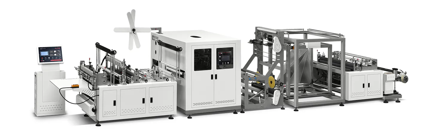
ZXL-A700背心袋无纺布制袋机.webp)
 English
  العربية
  Español
  Русский
  O‘zbekcha
  Қазақ тілі
  Português (AO90)
  Tiếng Việt
  (فارسی (افغانستان
  Kiswahili
  አማርኛ
አማርኛ  தமிழ்
தமிழ்  Bahasa Indonesia
  اردو
اردو  हिन्दी
  বাংলা
বাংলা